Inline foam inductors and foam concentrate equipment for fire suppression systems.


Inline foam inductors and foam concentrate equipment for fire suppression systems.
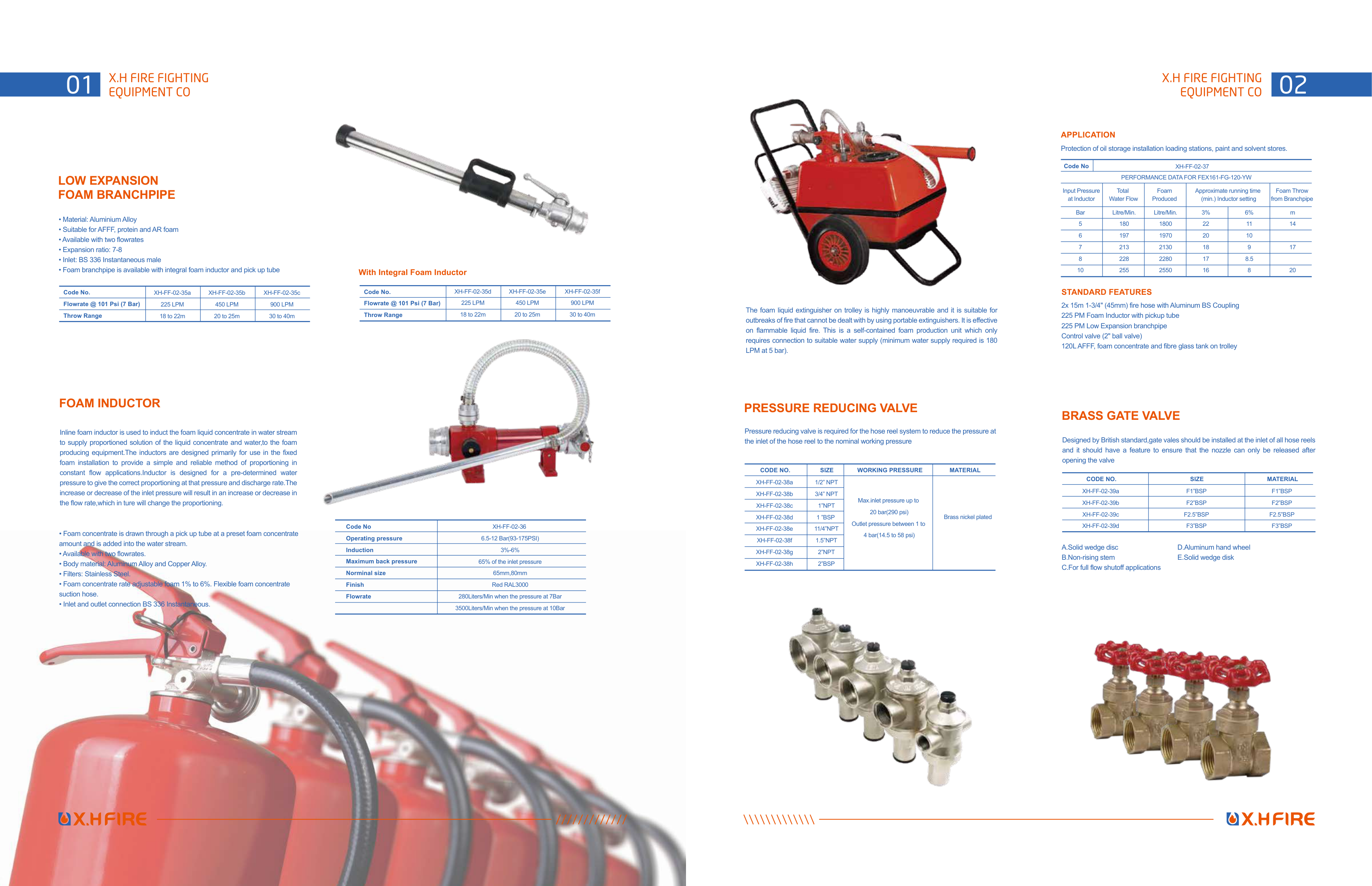
| FOAM INDUCTOR | |
| Inline foam inductor is used to induct the foam liquid concentrate in water stream | |
| to supply proportioned solution of the liquid concentrate and water,to the foam | |
| producing equipment.The inductors are designed primarily for use in the fixed | |
| foam installation to provide a simple and reliable method of proportioning in | |
| constant flow applications.Inductor is designed for a pre-determined water | |
| pressure to give the correct proportioning at that pressure and discharge rate.The | |
| increase or decrease of the inlet pressure will result in an increase or decrease in | |
| the flow rate,which in ture will change the proportioning. | |
| PRESSURE REDUCING VALVE | |
| Pressure reducing valve is required for the hose reel system to reduce the pressure at | |
| the inlet of the hose reel to the nominal working pressure | |
| The foam liquid extinguisher on trolley is highly manoeuvrable and it is suitable for | |
| outbreaks of fire that cannot be dealt with by using portable extinguishers. It is effective | |
| on flammable liquid fire. This is a self-contained foam production unit which only | |
| requires connection to suitable water supply (minimum water supply required is 180 | |
| LPM at 5 bar). | |
| Protection of oil storage installation loading stations, paint and solvent stores. | |
| APPLICATION | |
| Code No | |
| Operating pressure | |
| Induction | |
| Maximum back pressure | |
| Norminal size | |
| Finish | |
| Flowrate | |
| XH-FF-02-36 | |
| 6.5-12 Bar(93-175PSI) | |
| 3%-6% | |
| 65% of the inlet pressure | |
| 65mm,80mm | |
| Red RAL3000 | |
| 280Liters/Min when the pressure at 7Bar | |
| 3500Liters/Min when the pressure at 10Bar | |
| Code No | |
| XH-FF-02-37 | |
| PERFORMANCE DATA FOR FEX161-FG-120-YW | |
| Input Pressure | |
| at Inductor | |
| Total | |
| Water Flow | |
| Foam | |
| Produced | |
| Foam Throw | |
| from Branchpipe | |
| Approximate running time | |
| (min.) Inductor setting | |
| CODE NO. | |
| SIZE | |
| MATERIAL | |
| WORKING PRESSURE | |
| XH-FF-02-38a | |
| XH-FF-02-38b | |
| XH-FF-02-38c | |
| XH-FF-02-38d | |
| XH-FF-02-38e | |
| XH-FF-02-38f | |
| XH-FF-02-38g | |
| XH-FF-02-38h | |
| 1/2” NPT | |
| 3/4” NPT | |
| 1”NPT | |
| 1 ”BSP | |
| 11/4”NPT | |
| 1.5”NPT | |
| 2”NPT | |
| 2”BSP | |
| • Foam concentrate is drawn through a pick up tube at a preset foam concentrate | |
| amount and is added into the water stream. | |
| • Available with two flowrates. | |
| • Body material: Aluminum Alloy and Copper Alloy. | |
| • Filters: Stainless Steel. | |
| • Foam concentrate rate adjustable foam 1% to 6%. Flexible foam concentrate | |
| suction hose. | |
| • Inlet and outlet connection BS 336 Instantaneous. | |
| STANDARD FEATURES | |
| 2x 15m 1-3/4" (45mm) fire hose with Aluminum BS Coupling | |
| 225 PM Foam Inductor with pickup tube | |
| 225 PM Low Expansion branchpipe | |
| Control valve (2" ball valve) | |
| 120L AFFF, foam concentrate and fibre glass tank on trolley | |
| LOW EXPANSION | |
| FOAM BRANCHPIPE | |
| • Material: Aluminium Alloy | |
| • Suitable for AFFF, protein and AR foam | |
| • Available with two flowrates | |
| • Expansion ratio: 7-8 | |
| • Inlet: BS 336 Instantaneous male | |
| • Foam branchpipe is available with integral foam inductor and pick up tube | |
| With Integral Foam Inductor | |
| Code No. | |
| Flowrate @ 101 Psi (7 Bar) | |
| Throw Range | |
| XH-FF-02-35a | |
| 225 LPM | |
| 18 to 22m | |
| XH-FF-02-35b | |
| 450 LPM | |
| 20 to 25m | |
| XH-FF-02-35c | |
| 900 LPM | |
| 30 to 40m | |
| Code No. | |
| Flowrate @ 101 Psi (7 Bar) | |
| Throw Range | |
| XH-FF-02-35d | |
| 225 LPM | |
| 18 to 22m | |
| XH-FF-02-35e | |
| 450 LPM | |
| 20 to 25m | |
| XH-FF-02-35f | |
| 900 LPM | |
| 30 to 40m | |
| Bar | |
| 5 | |
| 6 | |
| 7 | |
| 8 | |
| 10 | |
| Litre/Min. | |
| 180 | |
| 197 | |
| 213 | |
| 228 | |
| 255 | |
| Litre/Min. | |
| 1800 | |
| 1970 | |
| 2130 | |
| 2280 | |
| 2550 | |
| 3% | |
| 22 | |
| 20 | |
| 18 | |
| 17 | |
| 16 | |
| 6% | |
| 11 | |
| 10 | |
| 9 | |
| 8.5 | |
| 8 | |
| m | |
| 14 | |
| 17 | |
| 20 | |
| Brass nickel plated | |
| Max.inlet pressure up to | |
| 20 bar(290 psi) | |
| Outlet pressure between 1 to | |
| 4 bar(14.5 to 58 psi) | |
| BRASS GATE VALVE | |
| Designed by British standard,gate vales should be installed at the inlet of all hose reels | |
| and it should have a feature to ensure that the nozzle can only be released after | |
| opening the valve | |
| CODE NO. | |
| SIZE | |
| MATERIAL | |
| XH-FF-02-39a | |
| XH-FF-02-39b | |
| XH-FF-02-39c | |
| XH-FF-02-39d | |
| F1”BSP | |
| F2”BSP | |
| F2.5”BSP | |
| F3”BSP | |
| F1”BSP | |
| F2”BSP | |
| F2.5”BSP | |
| F3”BSP | |
| A.Solid wedge disc | |
| B.Non-rising stem | |
| C.For full flow shutoff applications | |
| D.Aluminum hand wheel | |
| E.Solid wedge disk | |
